Low Frequency Noise In InGaAs Heterojunction FETs
Posted : 6 years, 4 months ago
InGaAs heterojunction FETs are magic parts—fast, strong, and extremely quiet. They're also called pseudomorphic high electron-mobility transistors (pHEMTs), because they use a 2D quantum well to to force the conduction electrons to move in a plane without much scattering. My fave Avago ATF38143 pHEMT was discontinued, but luckily Mini-Circuits stepped into the breach with their very nice SAV-551+ and its siblings, which are similar enough that the ATF SPICE model can be hacked up to work with them. (RF companies like Mini-Circuits never seem to supply SPICE models for some reason.) In one post on the 'purpose of precision' thread on sci.electronics.design, I noted that the Avago ATF38143 model I had posted awhile back predicted way, way too much low frequency noise. The real pHEMTs tend to have a pretty accurately 1/f PSD with corner frequencies between 10 and 50 MHz and flatband noise of around 0.3 nV/√Hz, about 10 dB quieter than the best JFETs, as well as being 20 times faster.
Their 1/f characteristic and very high transconductance makes them pretty good for bootstraps. Capacitive transducers such as photodiodes have admittances that rise with frequency, because Xc = 1/(2πf C). With an amplifier whose noise is flat, this produces a power spectral density (PSD) proportional to f2. (There's more on this in the docs for the QL01 from Hobbs ElectroOptics , my old photodiode front ends paper, or in Chapter 18 of Building ElectroOptical Systems.)
This extra noise gets a bit ugly at high frequency, but here it has the nice side effect of suppressing the low frequency noise: that factor of f2 squashes the 1/f noise pretty thoroughly, so these pHEMTs can be used at low frequencies with no issues. Their high transconductance makes them low output impedance followers, which is just what you need for a bootstrap. (Of course they can oscillate at frequencies as high as 12 GHz, so you do have to pay close attention to stability and good layout.)
Here's the old one:
.MODEL ATF38143_chip NMF( vto=-0.75, Beta=0.3, Lambda=0.07, Alpha=4,
+ B=0.8, Pb=0.7, Cgs=0.997E-12,
+ Cgd=0.176E-12, Rd=0.084, Rs=0.054, Kf=1e6, Af=1)
The relevant parameters are AF, which is the reciprocal of the noise exponent, and KF, which is the noise amplitude.
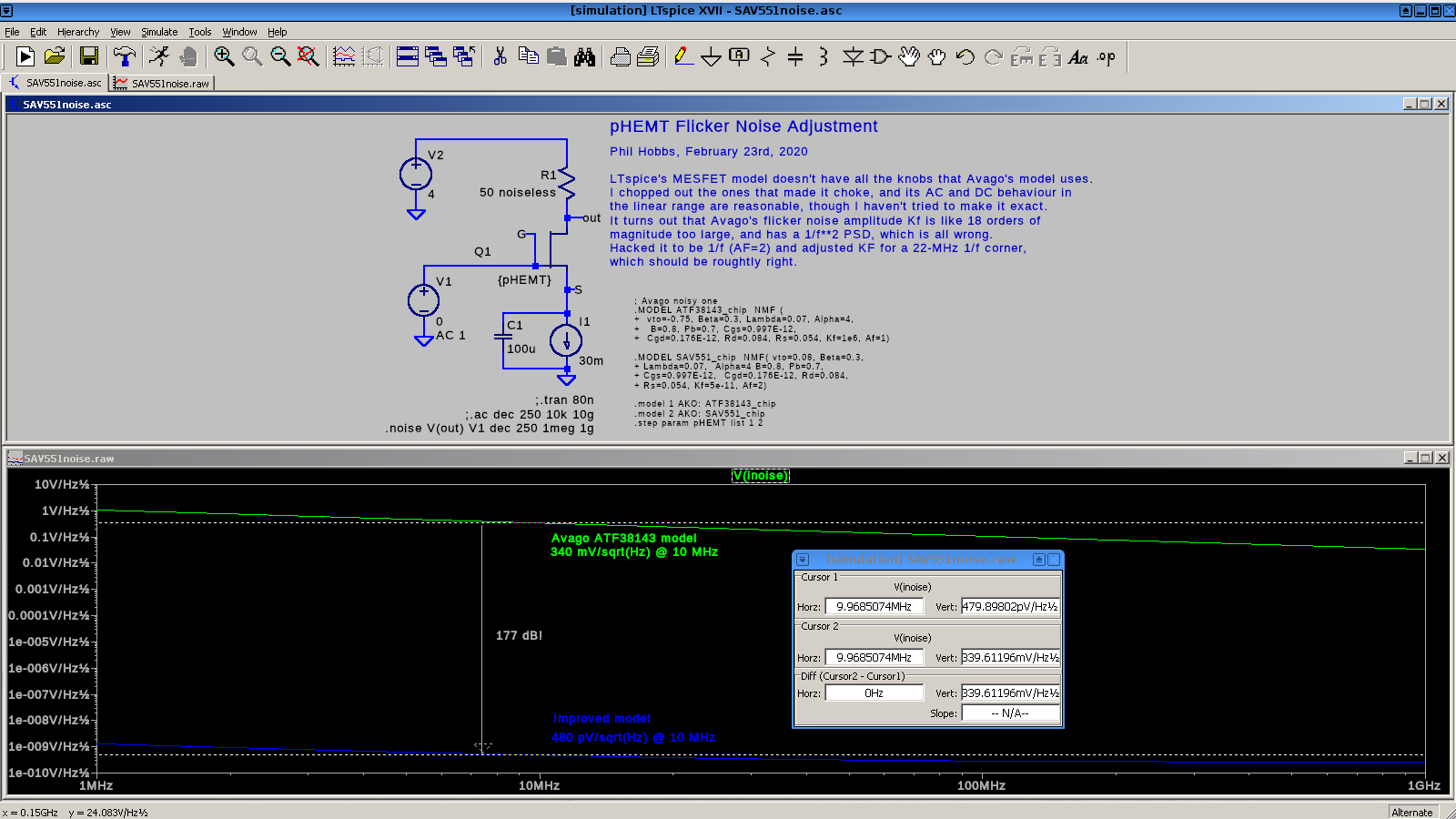
This produces a low-frequency noise power spectral density (PSD) that goes as 1/f2, and the noise at 10 MHz is 340 millivolts/sqrt(Hz), where with a 20-MHz corner frequency, it should be around 500 picovolts/sqrt(Hz). The PSD goes as the voltage squared, so at 10 MHz the old model is pessimistic by 20 log(0.34 V/500 pV) = 177 dB!
Here's the new one, with AF = 2, which gives a 1/f PSD, and KF = 5E-11, which gives a 1/f corner of 22 MHz. (VTO is also tweaked to make it an enhancement device.)
.MODEL SAV551_chip NMF( vto=0.08, Beta=0.3,
+ Lambda=0.07, Alpha=4 B=0.8, Pb=0.7,
+ Cgs=0.997E-12, Cgd=0.176E-12, Rd=0.084,
+ Rs=0.054, Kf=5e-11, Af=2)
Click on the image for the LTspice source file, sav551noise.asc.
Cheers
Phil Hobbs
Recent Posts
-
Featured Product: LA-22 Low Noise Lab Amplifier
-
 "Super-Regenerative Receivers" by J. R. Whitehead
 -
Temperature Control 1: Simple Control Theory
-
A High-Performance Time Domain Reflectometer
-
Product Announcement: QL03 Photoreceiver
Archive
2026
- January (1)
2025
2023
- May (1)
2021
- January (3)
2020
2018
2017
2015
2014
2013
2012
2011
Categories
- Design Support Consulting (8)
- Expert Witness Cases (15)
- New Technology (1)
- News (33)
- Products (4)
- SED (16)
- Sensitive Design (6)
- Ultrasensitive Instrument Design (27)
Tags
- photon budget (1)
- prototype (1)
- SEM (2)
- microscopy (1)
- microscope (1)
- product (1)
- noise (2)
- ultraquiet (1)
- thermoelectric cooler (1)
- Jim Thompson (1)
- analog-innovationscom (1)
- analog (2)
- ic design (1)
- scielectronicsdesign (1)
- website archive (1)
- MC4044 (1)
- MC1530 (1)
- SiPm (2)
- MPPC (2)
- PMT (1)
- Photomultiplier (2)
- frontend (1)
- module (2)
- hammamatsu (1)
- APD (2)
- SPAD (2)